ads 728x90

Highlight

Free Online Eagle PCB Library: Footprints & Layouts | Ultra Librarian: Simplify Your Design Process! Pcb library for eagle

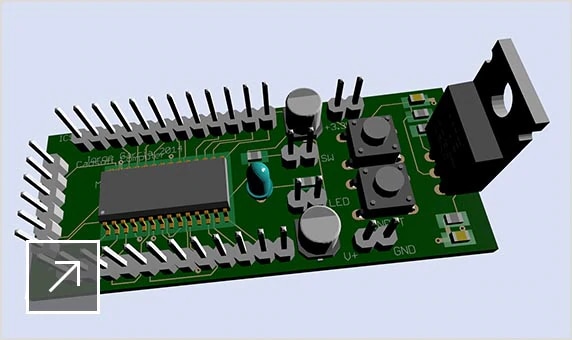
Ah, so you want to build electronics, yes? Very good! Like building with tiny Lego bricks, but with electricity! Very precise, very satisfyi...

Friday, April 18, 2025

Wika Pressure Transmitter 10 Wiring: Master Your Pressure Monitoring

When it comes to precise pressure monitoring in industrial applications, the Wika Pressure Transmitter stands out as a reliable choice. However, mastering the art of wiring this sophisticated device can be a daunting task for many technicians and engineers. In this blog post, we'll delve into the essential steps and tips for wiring the Wika Pressure Transmitter 10, ensuring you harness its full potential for accurate pressure measurements. Whether you're a seasoned professional or just starting in the field, our comprehensive guide will equip you with the knowledge you need to streamline your setup and enhance your monitoring capabilities.

Wika Pressure Transmitter S 10 Wiring Diagram

When it comes to mastering your pressure monitoring systems, understanding the wiring diagram for the Wika Pressure Transmitter S 10 is essential. This compact and robust transmitter is designed for precise measurement in various industrial applications, and its wiring setup plays a crucial role in ensuring accurate data transmission and device functionality. The S 10 wiring diagram typically includes clear indications for power supply connections, signal outputs, and grounding, allowing users to easily integrate the transmitter into their existing systems. By familiarizing yourself with this wiring diagram, you can enhance the reliability of your pressure measurements and streamline your installation process, ultimately leading to improved operational efficiency.

Wika pressure transmitter s 10 wiring diagram www.circuitdiagram.co

Pressure Transmitter Wika A-10

The Wika A-10 pressure transmitter is a robust and reliable solution for precise pressure monitoring in various industrial applications. Known for its exceptional accuracy and durability, the A-10 features a compact design that makes it easy to install in tight spaces. With a wide measuring range and excellent temperature stability, this transmitter ensures consistent performance even in challenging environments. Understanding the wiring of the Wika A-10 is crucial for maximizing its potential; proper connections not only enhance functionality but also ensure safety and compliance with industry standards. In this blog post, we will delve into the specifics of wiring the Wika A-10 pressure transmitter, empowering you to master your pressure monitoring needs effectively.

Pressure transmitter wika a-10 www.automation24.co.uk

Wika Pressure Transmitter A 10 Wiring Diagram

When it comes to mastering pressure monitoring, understanding the Wika pressure transmitter 10 wiring diagram is essential for ensuring accurate and reliable readings. This diagram provides a clear visual representation of how to connect the transmitter to your system, including the power supply, signal output, and grounding requirements. By following the Wika pressure transmitter 10 wiring guidelines, you can effectively integrate the device into your application, whether it's for industrial processes, HVAC systems, or any other pressure measurement needs. Familiarizing yourself with this wiring configuration not only simplifies installation but also enhances the overall performance and longevity of your pressure monitoring setup.

Wika pressure transmitter a 10 wiring diagram diysica.blogspot.com

[diagram] Wika Pressure Transmitter Wiring Diagram

When it comes to mastering your pressure monitoring systems, understanding the Wika pressure transmitter wiring diagram is essential. This diagram serves as a visual guide, illustrating the connections between the transmitter and other components in your setup. By following the wiring diagram carefully, you can ensure accurate readings and reliable performance from your pressure transmitter. It typically includes key elements such as power supply connections, output signals, and grounding points, which are vital for maintaining signal integrity and preventing interference. Whether you're a seasoned technician or a novice, familiarizing yourself with this wiring diagram will empower you to efficiently install and troubleshoot your Wika pressure transmitter, ultimately enhancing the reliability of your pressure monitoring applications.

[diagram] wika pressure transmitter wiring diagram mydiagram.online

Wika Pressure Transmitter

When it comes to precision in pressure monitoring, the Wika pressure transmitter stands out as a reliable choice for various industrial applications. Its advanced technology ensures accurate measurement and consistent performance, making it an essential tool for engineers and technicians alike. Understanding the wiring of the Wika pressure transmitter is crucial for optimal functionality and safety. In this blog post, we will delve into the intricacies of the 10 wiring configurations, providing you with a comprehensive guide to master your pressure monitoring setup. Whether you're integrating it into a new system or troubleshooting an existing one, our insights will help you navigate the complexities of wiring, ensuring you get the most out of your Wika pressure transmitter.

Wika pressure transmitter mungfali.com

Thursday, April 17, 2025

7 Prong Trailer Wiring Diagram Ford: Master Your Towing Setup!

When it comes to towing with your Ford vehicle, understanding the intricacies of a 7 prong trailer wiring diagram is essential for a seamless and safe towing experience. Whether you're hauling a boat, camper, or utility trailer, the right wiring setup ensures that your lights, brakes, and other essential functions work harmoniously. In this guide, we'll break down the components of a 7 prong trailer wiring diagram specific to Ford trucks and SUVs, empowering you to master your towing setup and hit the road with confidence. Get ready to dive into the world of trailer wiring and transform your towing capabilities!

Typical Boat Trailer Wiring Diagram

When it comes to towing, understanding the typical boat trailer wiring diagram is crucial for ensuring a safe and efficient connection between your vehicle and the trailer. A standard 7-prong wiring setup typically includes connections for tail lights, turn signals, brake lights, and a ground wire, along with additional features like a 12V power supply and reverse lights. Familiarizing yourself with this wiring diagram not only helps in troubleshooting any electrical issues but also ensures that all lights and signals function properly while on the road. Whether you're a seasoned boater or a novice, mastering the wiring diagram is an essential step in optimizing your towing setup for a smooth and hassle-free experience.

Typical boat trailer wiring diagram wiringdiagramall.blogspot.com

Wiring Diagram Of 7 Pin Trailer Plug Diagrams

When it comes to towing, understanding the wiring diagram for a 7 pin trailer plug is essential for a seamless connection between your vehicle and trailer. The 7 prong trailer wiring diagram for Ford vehicles typically includes connections for various functions such as tail lights, brake lights, turn signals, and electric brakes. Each pin serves a specific purpose, ensuring that your trailer operates safely and efficiently on the road. By mastering this wiring setup, you can confidently tackle any towing job, knowing that your trailer's lighting and braking systems are properly configured. Whether you're a seasoned hauler or new to towing, familiarizing yourself with the 7 pin trailer wiring diagram will enhance your overall towing experience and ensure compliance with safety regulations.

Wiring diagram of 7 pin trailer plug diagrams www.thesecularparent.com

Step-by-step Guide: Wiring Diagram For A 7 Pin To 5 Pin Trailer Connector

In this step-by-step guide, we will walk you through the wiring diagram for converting a 7-pin trailer connector to a 5-pin configuration, ensuring that your towing setup is both safe and efficient. First, gather your materials: a 7-pin connector, a 5-pin connector, wire strippers, and electrical tape. Begin by identifying the function of each pin on the 7-pin connector, which typically includes functions like tail lights, brake lights, turn signals, and ground. Next, refer to the wiring diagram to match the appropriate wires from the 7-pin connector to the corresponding pins on the 5-pin connector. For instance, the tail light wire from the 7-pin should connect to the tail light pin on the 5-pin. After making all the necessary connections, secure them with electrical tape to prevent any exposure to moisture or corrosion. Finally, test your connections with a multimeter to ensure everything is functioning correctly before hitting the road. Following this guide will help you master your towing setup and ensure a hassle-free experience on your journeys.

Step-by-step guide: wiring diagram for a 7 pin to 5 pin trailer connector autoctrls.com

Wiring Diagram Trailer Brakes

When it comes to mastering your towing setup, understanding the wiring diagram for trailer brakes is crucial, especially when working with a 7-prong trailer wiring system on Ford vehicles. The wiring diagram outlines the specific connections needed to ensure that your trailer's braking system operates effectively and safely. Typically, the brake signal is transmitted through the blue wire in the 7-prong connector, which activates the trailer's electric brakes when the tow vehicle's brake pedal is pressed. Familiarizing yourself with this diagram not only helps in troubleshooting potential issues but also ensures compliance with safety regulations, providing peace of mind while you're on the road. Whether you're a seasoned tower or a novice, knowing how to connect and maintain your trailer brakes can significantly enhance your towing experience.

Wiring diagram trailer brakes www.flowschema.com

Towbar Trailer Plug Wiring Diagram

When it comes to towing with your Ford, understanding the 7 prong trailer wiring diagram is essential for ensuring a safe and efficient connection between your vehicle and trailer. The towbar trailer plug wiring diagram outlines the specific functions of each pin, including the essential features such as tail lights, brake lights, turn signals, and electric brakes. Familiarizing yourself with this wiring diagram not only simplifies the installation process but also helps troubleshoot any electrical issues that may arise during towing. Whether you're a seasoned hauler or a first-time tower, mastering the intricacies of your towbar wiring can enhance your towing experience and provide peace of mind on the road.

Towbar trailer plug wiring diagram organicic4.blogspot.com

Coil Tattoo Machine Diagram: Understand Your Tattoo Gear

When it comes to the art of tattooing, understanding your tools is just as important as mastering your technique. One of the essential instruments in any tattoo artist's arsenal is the coil tattoo machine. This intricate device combines mechanical engineering with artistic expression, allowing artists to create stunning designs on skin. In this blog post, we'll delve into the anatomy of a coil tattoo machine, breaking down its components and functions through a detailed diagram. Whether you're a seasoned tattoo artist or a curious enthusiast, grasping the inner workings of this machine will enhance your appreciation for the craft and improve your skills. Let's get started!

[diagram] Wireless Tattoo Machines Diagram

In the world of tattooing, understanding your equipment is crucial for achieving the best results, and a wireless tattoo machine diagram can be particularly enlightening. This diagram illustrates the key components of a wireless tattoo machine, highlighting elements such as the battery pack, motor, and needle configuration. By visualizing how these parts work together, tattoo artists can gain insights into the mechanics behind their gear, enhancing their technique and efficiency. Whether you're a seasoned professional or just starting out, familiarizing yourself with the wireless tattoo machine diagram will empower you to make informed decisions about your tools, ultimately leading to better artistry and client satisfaction.

[diagram] wireless tattoo machines diagram mydiagram.online

How To Build Coil Tattoo Machine

Building a coil tattoo machine can be an exciting project for aspiring tattoo artists and enthusiasts alike. To start, you'll need essential components such as the frame, coils, armature bar, and a power supply. Begin by assembling the frame, ensuring it's sturdy enough to withstand the vibrations during use. Next, attach the coils, which are crucial for generating the electromagnetic field that powers the machine; typically, you'll use two coils wound with copper wire. The armature bar, connected to the needle, should be positioned correctly to ensure smooth movement and accurate ink delivery. It's important to pay attention to the diagram of your machine, as it will guide you through the wiring and assembly process. By carefully following the diagram and understanding each component's function, you can create a reliable coil tattoo machine that will help you bring your artistic visions to life.

How to build coil tattoo machine diagramlibraryconjoin.z19.web.core.windows.net

Top More Than 78 Coil Tattoo Machine Diagram Super Hot

When diving into the world of tattoo artistry, understanding the intricacies of your equipment is crucial, and the coil tattoo machine stands out as a classic choice among professionals. With over 78 different coil tattoo machine diagrams available, artists can explore a variety of designs and configurations that cater to their unique style and technique. Each diagram illustrates the fundamental components—such as the coils, armature bar, and frame—allowing both beginners and seasoned tattooists to grasp how these machines operate. By studying these diagrams, tattoo artists can optimize their gear for better performance, ensuring precise lines and vibrant ink application. Whether you're looking to customize your machine or simply enhance your skills, these diagrams serve as an invaluable resource in mastering the art of tattooing.

Top more than 78 coil tattoo machine diagram super hot in.coedo.com.vn

Complete Guide On Tattoo Machines

When diving into the world of tattooing, understanding your equipment is crucial, and the coil tattoo machine stands out as a favorite among many artists for its reliability and versatility. In this complete guide on tattoo machines, we'll break down the essential components of the coil tattoo machine, including its electromagnetic coils, armature bar, and needles, providing you with a clear diagram to visualize how each part functions together. Whether you're a seasoned professional or a beginner looking to enhance your skills, grasping the mechanics behind your tattoo gear will not only improve your technique but also elevate the quality of your artwork. Join us as we explore the intricacies of coil machines, ensuring you have the knowledge to make informed choices for your tattooing journey.

Complete guide on tattoo machines tattooing101.com

Wiring Diagram For A Coil Tattoo Machine

Understanding the wiring diagram for a coil tattoo machine is crucial for both beginners and seasoned tattoo artists alike. This diagram serves as a blueprint, illustrating how the various components of the machine are interconnected to create the perfect tattooing experience. Typically, a coil tattoo machine consists of a power source, coils, a frame, an armature bar, and a needle assembly, all of which work in harmony to deliver precise ink application. By studying the wiring diagram, artists can troubleshoot issues, customize their machines for different techniques, and ensure that their gear operates efficiently. Whether you're looking to build your own machine or simply want to grasp the mechanics behind your current setup, mastering the wiring diagram is an essential step in enhancing your tattoo artistry.

Wiring diagram for a coil tattoo machine elecsprout.com

Wednesday, April 16, 2025

Motor Wiring Diagram Single Phase: Fix Your Motor Like A Pro

When it comes to maintaining and repairing electric motors, understanding the wiring diagram is crucial for both professionals and DIY enthusiasts alike. A single-phase motor wiring diagram is your roadmap to troubleshooting and fixing common issues that can arise in these essential machines. Whether you're dealing with a malfunctioning motor in your home appliance or a critical component in your workshop, knowing how to interpret and utilize these diagrams can empower you to tackle repairs like a pro. In this blog post, we'll break down the essentials of single-phase motor wiring diagrams, providing you with the knowledge and confidence to get your motor running smoothly again.

220v Single Phase Motor Wiring Diagram

When it comes to understanding a 220V single phase motor wiring diagram, having a clear visual representation is essential for both troubleshooting and installation. Typically, these diagrams illustrate the connections between the motor's terminals, the power supply, and any control components, such as capacitors or switches. A single phase motor usually features two main terminals: the line (L) and the neutral (N), along with a start capacitor that aids in initiating the motor's operation. By following the wiring diagram step-by-step, you can ensure that your connections are secure and correctly configured, allowing your motor to operate efficiently. Whether you're replacing an old motor or wiring a new one, mastering this diagram will empower you to tackle motor repairs like a pro, ensuring optimal performance and longevity.

220v single phase motor wiring diagram annawiringdiagram.com

Single Phase Motor Circuit Diagram

When working with a single-phase motor, understanding the circuit diagram is crucial for effective troubleshooting and repairs. A single-phase motor circuit diagram typically includes essential components such as the motor itself, a capacitor (if applicable), a switch, and the power supply. The diagram illustrates how these elements are interconnected, allowing for a clear understanding of the flow of electricity. By familiarizing yourself with the wiring layout, you can diagnose issues like motor failure or improper operation more efficiently. Whether you're a DIY enthusiast or a professional technician, mastering the single-phase motor circuit diagram will empower you to fix your motor like a pro, ensuring optimal performance and longevity.

Single phase motor circuit diagram www.mikrora.com

Single Phase Motor Forward Reverse Wiring Diagram Col

When it comes to understanding the wiring of single-phase motors, mastering the forward and reverse wiring diagram is essential for both professionals and DIY enthusiasts. This diagram illustrates how to connect the motor's terminals to achieve the desired rotational direction. Typically, a single-phase motor features two main windings: the start winding and the run winding. By swapping the connections of these windings, you can easily reverse the motor's direction. It's crucial to follow the wiring diagram carefully, ensuring all connections are secure and correctly positioned to avoid any short circuits or damage. With the right knowledge and tools, you can confidently fix your motor and optimize its performance like a pro.

Single phase motor forward reverse wiring diagram col www.vrogue.co

Schematic Diagram Of Three Phase Motor

When tackling motor wiring diagrams, understanding the schematic diagram of a three-phase motor is crucial for any DIY enthusiast or professional looking to fix their motor like a pro. A three-phase motor operates using three alternating currents, which are offset by 120 degrees, providing a smoother and more efficient power delivery compared to single-phase motors. In the schematic diagram, you'll typically find representations of the motor windings, connections to the power supply, and protective devices such as circuit breakers or fuses. By familiarizing yourself with these components, you can troubleshoot issues, ensure proper connections, and maintain optimal performance in your motor systems. Whether you're replacing a faulty part or upgrading your setup, a clear understanding of the three-phase motor schematic will empower you to make informed decisions and enhance your motor repair skills.

Schematic diagram of three phase motor origaninc2mguidepart.z21.web.core.windows.net

Wiring 3 Phase Motor To Single Phase

Wiring a three-phase motor to operate on single-phase power can seem daunting, but with the right guidance, you can tackle this task like a pro. The key lies in understanding the motor's configuration and the specific requirements for converting it to single-phase operation. Typically, this involves using a capacitor or a phase converter to create a second phase, ensuring that the motor runs smoothly and efficiently. It's essential to follow a detailed wiring diagram tailored for your motor type, as this will help you identify the correct connections and components needed for the conversion. By carefully following these steps, you can successfully wire your three-phase motor to single-phase power, allowing you to maximize your motor's potential in a home or small workshop setting.

Wiring 3 phase motor to single phase schematicpepper.z13.web.core.windows.net